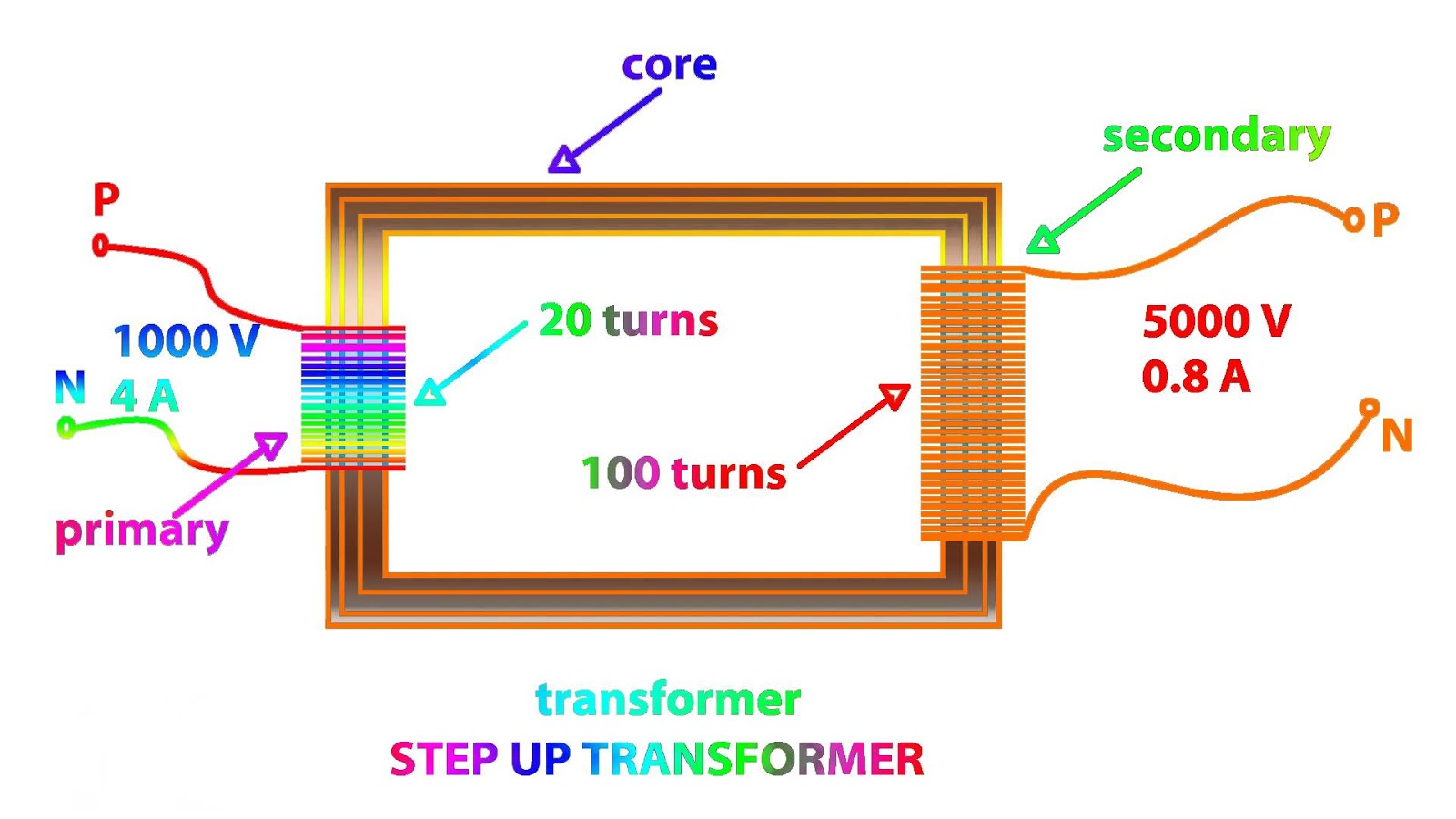
Step Up Transformer Wiring Diagrams Circuit Diagram In this electronics 101 series episode, I get into what step up and step down transformers are, how they work (electromagnetic induction), what we humans us Step-down transformer: (many turns :few turns). The step-up/step-down effect of coil turn ratios in a transformer (Figure above) is analogous to gear tooth ratios in mechanical gear systems, transforming values of speed and torque in much the same way: (Figure below) Torque reducing gear train steps torque down, while stepping speed up. Schematic diagram of the transformer. A schematic diagram of a step-up transformer is shown in image 2, wi th T 1 and T 2 representing the turns of the primary and secondary windings and V 1 and V 2 representing the in put and output voltages, respectively. The transformer's output winding is the secondary winding, whereas the primary winding is the transformer's input winding.
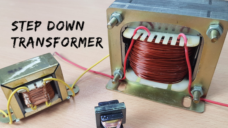
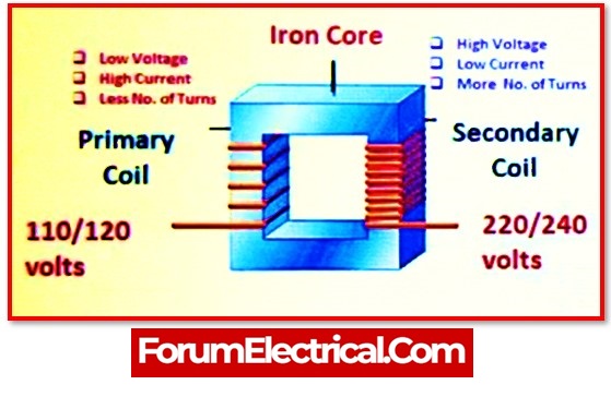
A transformer designed to reduce the voltage from primary to secondary is called a step-down transformer. The transformation ratio of a transformer will be equal to the square root of its primary to secondary inductance (L) ratio. RELATED WORKSHEETS: Step-up, Step-down, and Isolation Transformers Worksheet
DC Boost Converter (Step Up) : 5 Steps Circuit Diagram
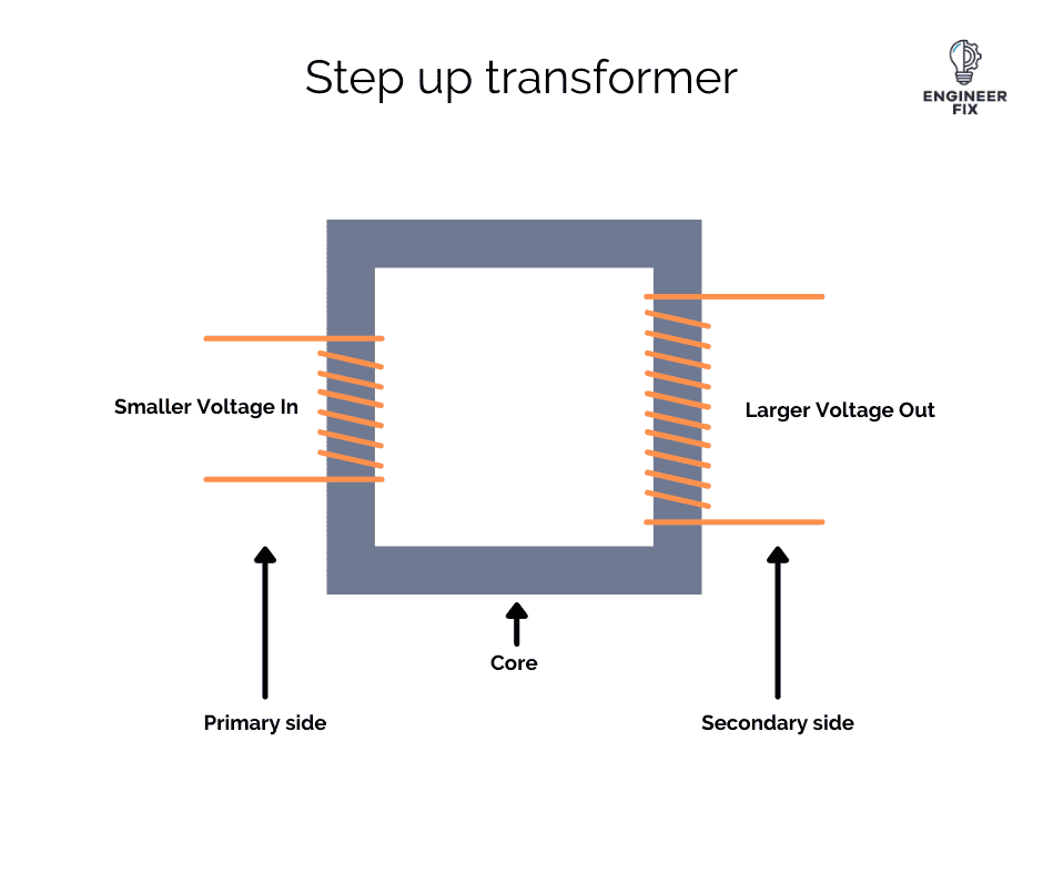
Figure 1: step up transformer wiring diagram . What does a Step-up Transformer Do. Step-up transformers are used in electronic devices like inverters, batteries, and stabilizers to balance low and higher voltages in transformers. They are used in power transmission, playing a crucial role in transferring power to locations far from generating Step-Up Transformer Simulation. A step-up transformer that increases the voltage from the primary winding to the secondary winding. The secondary winding consists of more turns than the primary winding. Step-up transformers are widely used in inverter and booster applications that convert low voltage to the desired high voltage. Circuit Diagram A boost converter (step-up converter) is a DC-to-DC power converter that steps up voltage (while stepping down current) from its input (supply) to its output (load). It is a class of switched-mode power supply (SMPS) containing at least two semiconductors (a diode and a transistor) and at least one energy storage element: a capacitor, inductor
Key learnings: Step Up Transformer Definition: A step-up transformer is a device that increases the voltage while decreasing the current from its primary to its secondary side.; Working Principle: It operates by converting electrical energy to magnetic energy and back, utilizing the transformer core.; Voltage Transformation Formula: The formula for output voltage in a step-up transformer shows