Experiment 4 Filter Circuits 1 Design and Circuit Diagram Active Low-Pass Filter Design Jim Karki AAP Precision Analog ABSTRACT This report focuses on active low-pass filter design using operational amplifiers. Low-pass filters are commonly used to implement anti-aliasing filters in data acquisition systems. Design of second-order filters is the main topic of consideration.
The formula and schematic for the LC low pass filter: Let's analyze a low pass filter with a practical example : Q. Design a low pass filter having cutoff frequency 'fc' = 75MHz and Vin = 5 volts using RC filter? Solution: given -> f = 75Mhz. R = 100 Ω(assumed)——-
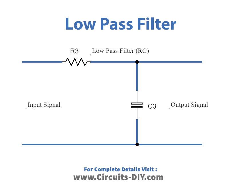
Low Pass Filter Calculator Circuit Diagram
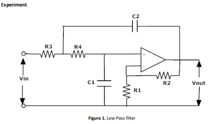
To surmount this problem, active circuit designs were introduced. When a passive low pass filter is connected to an Op-Amp either in inverting or non-inverting condition, it gives an active low pass filter design. The connection of a simple RC circuit with a single Op-Amp is shown in the image below.. First Order Active Low Pass Filter with the frequency response
The following images depict the standard opamp based low pass filter circuits. The first one needs to be powered by a dual supply, and the second one works using a single supply voltage. Designing a Customized Low Pass Filter Circuit Just want some suggestion design low pass filter circuit for my 40w-4ohms speaker as my subwoofer, thanks. Posted on September 09th 2022 | 10:00 pm. Reply. Karthick R. Can remove low and high pass filter from amp board. Posted on August 31st 2022 | 10:33 am. Reply. John. Whether you're designing an entire sound system complete with a bass boost, or just want to remove high-frequency noise, the low-pass filter calculator can help you create the perfect low-pass filter circuit for your needs. Read on to learn: What a low-pass filter is; The difference between passive and active low-pass filters; and

Lowpass Filter Circuit Design: Avoid These Common Mistakes Circuit Diagram
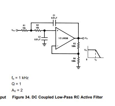
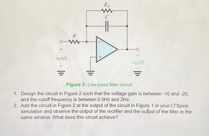
Active Low Pass Filter Example No1. Design a non-inverting active low pass filter circuit that has a gain of ten at low frequencies, a high frequency cut-off or corner frequency of 159Hz and an input impedance of 10KΩ. The voltage gain of a non-inverting operational amplifier is given as: