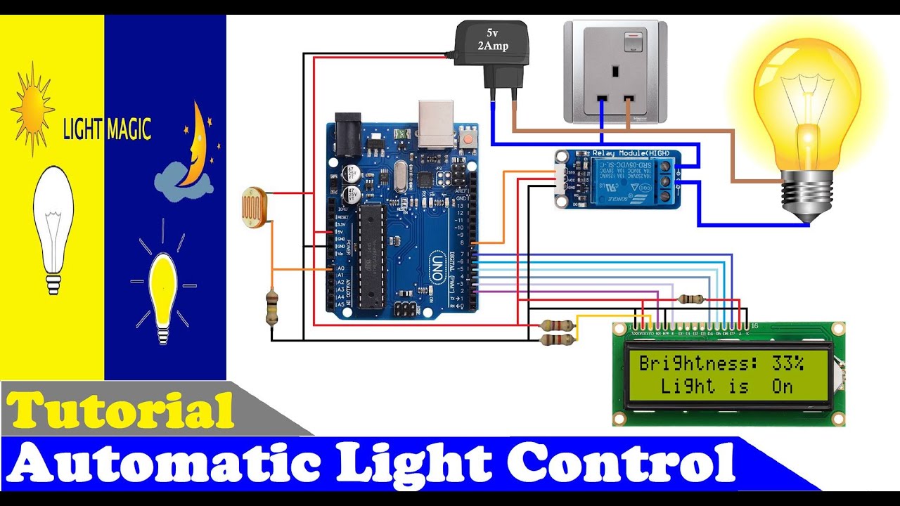
Automatic Light Detector Circuit Diagram We built an automatic light switch that turns on or off a light source based on the ambient light conditions. This can be useful in saving energy by automatically controlling the lighting in a room. We also built a regulated light system, where the intensity of a light source is adjusted based on the surrounding light conditions. How to Make This Automatic Street Light Circuit Step by Step Right Here. Alright. Now we will see how we can make this street light system right. We will do it step by step. So no confusion, no problem, all clear, right. Even if someone is totally new, they can do it, okay. Step 1: Get All the Parts First. No Parts, No Circuit, Right.

Name: Arduino-Powered Automatic Light System. Category: . Type: . Summary - oneliner: A hands-on project to build an automatic light system that controls itself based on ambient light using Arduino and a Light Dependent Resistor (LDR).. Purpose: To teach Arduino programming, sensor integration, and basic electronics by creating a practical automatic lighting system, which can be applied to A simple automatic streetlight, etc; It can also be used along with other sensors to do pretty cool stuff. I am assuming at this point you know very little about Arduino and so I have tried to simplify and explain everything so that you can easily understand. Basically, the LDR senses the amount of light around and tells the Arduino. The Perfect Automatic Lighting System Using Arduino + LDR + PIR: In this project,We will set up an automatic lighting system using arduino, so the ideas came when I tried to build automatic lighting system using arduino and PIR motion sensor but I confronted big issue because the light turn ON even if daytime,thi…
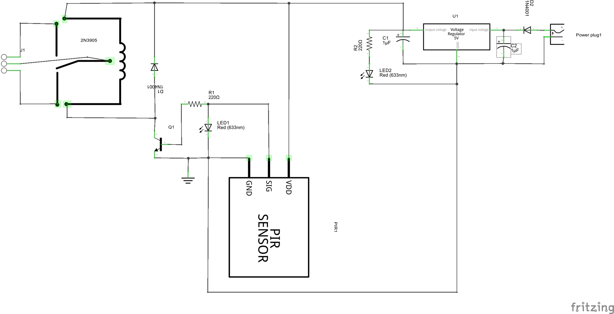
Making an Automatic Street Light using just two Transistors and a Relay Circuit Diagram
Arduino light sensor: Conclusion. In this beginner Arduino light sensor project, you learned how to use a light dependent resistor to sense light levels and interface it with an Arduino board. By connecting the LDR in a voltage divider circuit and reading the analog values, you are able to monitor how its resistance changes in response to light. Ensure the switch is compatible with the existing wiring system. Step 4: Configure the Sensors. Use the sensor's app or control panel to configure settings. This might involve setting the sensitivity, adjusting the time delay before lights turn off, and integrating with your smart home system for remote control. Step 5: Test Your Setup Connecting the Arduino Light Sensor on a Breadboard. Here's how you can connect this circuit to an Arduino by using a breadboard and some cables: Arduino Light Sensor Code. This Arduino code is an example of reading the voltage from the light sensor (connected to analog pin A0) and then printing the value of the analog reading to the Serial