AFIATACOM Electronic Circuit Circuit Diagram Diy Headphone Amp Schematic: A Guide to Building Your Own. Building your own headphone amp can be a rewarding and cost-effective project for audio enthusiasts. By following a diy headphone amp schematic, you can customize the amp to your preferences and create a high-quality sound reproduction system for your headphones.

This is a headphone amplifier similiar to the one designed by Chu Moy. For reference, the original Chu Moy article is here while a great tutorial on building it is here.I have used a different dual operational amplifier, the RC4560, manufactured by Texas Instruments, in the TSSOP package, and chip resistors in order to make an extremely small printed circuit board assembly.
Building your own headphone amp: a detailed schematic Circuit Diagram
The circuit diagram of the LM4910 stereo headphone amplifier is witnessed above. C1 and C2 are actually the input DC decoupling capacitors for the left together with right input channels. R1 along with R2 tend to be the individual input resistors. R3 is the feed back resistor for left channel whereas R4 is the feed back resistor for the right
I test this circuit using my Sennheiser HD201 headphones, they are quite efficient and sound pretty tasty with this circuit! :P It only uses a handful of components which most electronics builders can find in their component boxes etc. This circuit can work on any voltage from 6v-24v aslong as heatsinking the components is taken into consideration.
Easy to Build Headphone Amplifier Using Mosfets Circuit Diagram
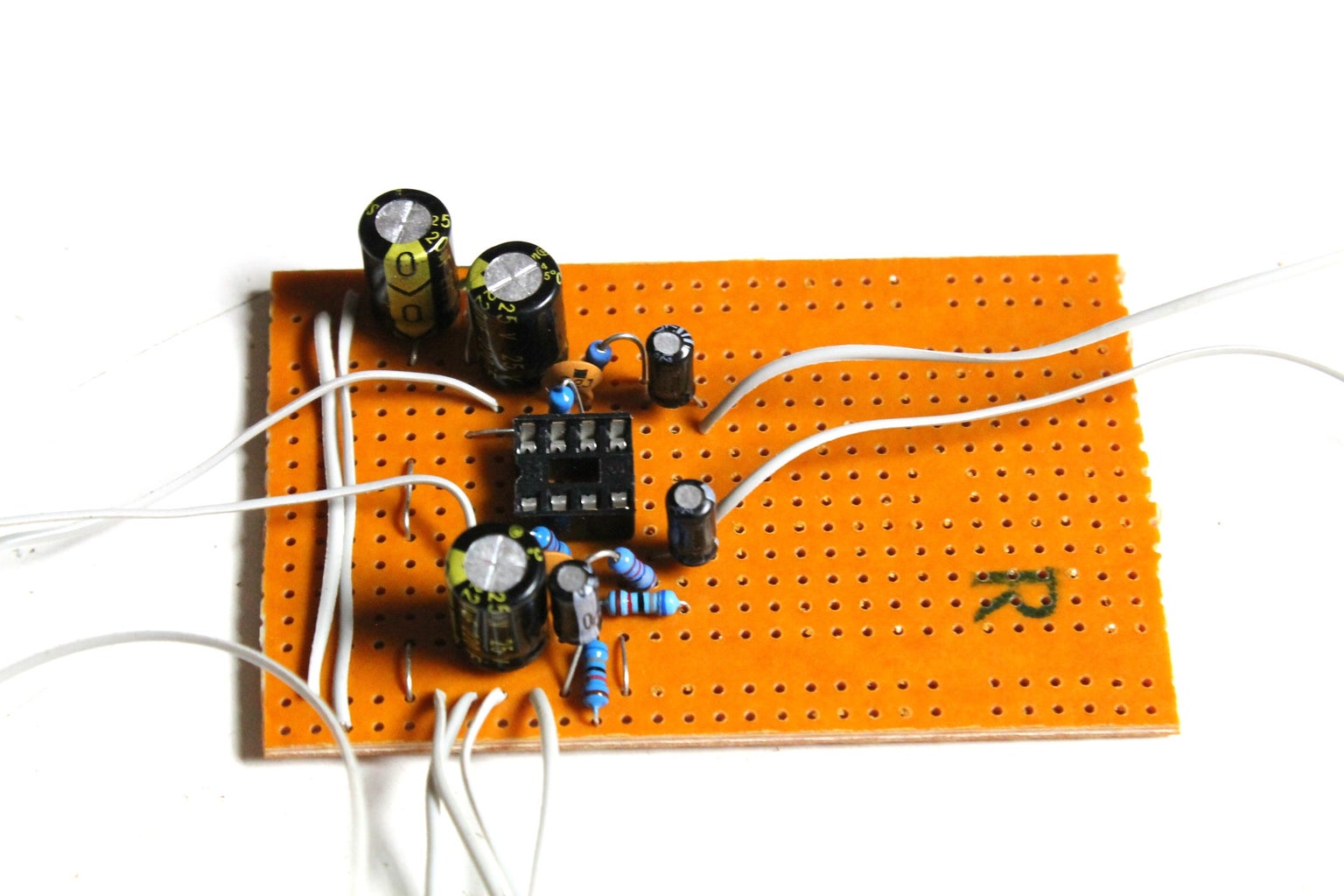
Make a Headphone Amp V2: After discovering Cew27's Cmoy Headphone Amp a few months ago on Instructables, I've been inspired to build my own. I was also inspired by Koogars amazing Crystal CMoy Free Form Headphone Amplifier which I have been admiring for a few years now. First thing to do is to take a good look at the circuit design and
